Different types of cryogenic vessels: vacuum-insulated /non-vacuum-insulated, static/transportable
Used for more than 40 years for storage and
transportation of industrial and medical gases
In a volume of 1L of liquid, about 800L of gas can be stored
The gases need to be refrigerated to very low temperatures to be liquid.
3 Scope and Purpose
3.1 Scope This document considers the periodic inspection and testing of static vacuum-insulated cryogenic pressure vessels that store refrigerated liquefied gases, excluding toxic gases. The design and materials used to construct these vessels include carbon dioxide and nitrous oxide. It does not consider the vessels/equipment directly used in producing these products or those used for transport, covered by the Transport Pressure Equipment Directive (TPED) or transportation of dangerous goods, e.g., ADR in Europe.
3.2 Purpose This document considers the influence of periodic inspection and testing of static vacuum-insulated cryogenic pressure vessels on their continuing safety, as the industrial gases industry’s underlying concern is the safe operation of all its equipment. It also extensively reviews existing national regulations in Europe.
4 Technical Background
4.1 Production The basic process for producing oxygen, nitrogen, and argon requires compression, cooling, purification, liquefaction, and air distillation, which occur at cryogenic temperatures. The gases formed in vapour or liquid are non-corrosive, non-toxic, and non-flammable. Air contains these gases in the following percentages: oxygen (21%), nitrogen (78%), and argon (0.9%). The balance (0.1%) includes water, carbon dioxide, rare gases, and other impurities in tiny quantities. While none of the gases is toxic, reducing oxygen levels below normal can cause asphyxiation. Increased oxygen concentrations can accelerate, but not initiate, the combustion of other materials. The process is directed to the production of gaseous and liquid products. In its simplest form, compressed and cooled air is purified and cooled to liquefaction temperatures in the passes of a heat exchanger against waste nitrogen and pure product gases.
Impurities such as small traces of CO2 or hydrocarbon contaminants being carried by air are
removed before introduction into the column.
The careful and essential purification of the process streams ensures that the cryogenic fluids
produced do not contain elements that could initiate corrosion.
The compressed air at liquefaction temperature is then distilled in a column. The column and
associated process vessels separate the air into its major constituents, which are drawn off as
gaseous and liquid products. These products are icy, at high levels of purity, and by the nature
of the process, are free from water vapour.
Impurities such as small traces of CO2 or hydrocarbon contaminants being carried by air are removed before introduction into the column. The careful and essential purification of the process streams ensures that the cryogenic fluids produced do not contain elements that could initiate corrosion. The compressed air at liquefaction temperature is then distilled in a column. The column and associated process vessels separate the air into its major constituents, which are drawn off as gaseous and liquid products. These products are very cold, at high levels of purity, and by the nature of the process, are free from water vapour.
Table 1. Typical Physical Properties.

4.2 Pressure Vessel
For the purposes of this document, pressure equipment is defined, as in the PED, with a maximum allowable pressure of more than 0.5 bar. The PED excludes pressure equipment < 0.5 bar.
Vaporizers are categorized as pressure vessels.
4.2.1 Cryogenic Vessel
Static vacuum-insulated cryogenic vessels usually have a capacity of less than 400,000 liters. The inner vessel contains the liquefied gas under pressure, represents the actual pressure vessel, and is designed to withstand internal pressure, external vacuum, and cryogenic temperatures. The inner vessel is surrounded by an enclosure in the form of a jacket within which a vacuum is maintained to achieve the necessary degree of insulation between the surface of the jacket and the enclosed vessel. The inner vessel is of simple cylindrical shape with dished or spherical heads. The vacuum interspace is filled with an insulating material. The vacuum jacket acts as insulation containment and the support structure for the inner vessel. It is manufactured from carbon steel and is not usually classified as a pressure vessel. In the event that the inner vessel leaks the vacuum jacket pressure relief device operates to avoid damage. These vessels are installed at customer premises and together with other equipment are known as cold converters or customer stations. For the purposes of this document, they are referred to as vacuum-insulated cryogenic vessels. Vacuum-insulated storage vessels operate at reasonably constant working pressures with only very occasional total de-pressurization and re-pressurization. The liquid space temperature remains almost constant. Only small external loads are applied to the inner vessel from pipework as it is designed to avoid stresses occurring due to contraction or expansion on cool-down or warm-up. Supports and anchor bars from the inner vessel to the outer jacket are designed to provide minimum heat transfer. The loss of vacuum in the interspace usually is not a safety problem if it occurs during tank operation; the additional insulation material used is sufficient to keep the vessel contents’ evaporation rate within the inner vessel relief valves’ average rating. Any loss of vacuum should be investigated, as this could affect the integrity of the vessel and support system.
4.2.2 Cryogenic Vaporisers
All cryogenic vaporizers are of tubular construction and transfer heat to obtain vaporization of the cryogenic liquid using ambient air, water, steam, or other hot liquids or gases. AIGA 046/08 3 Some vaporizers are normal heat exchangers of shell and tube type well known and proven over many years in the chemical industry, designed, fabricated, and tested in accordance with recognized pressure vessel codes. In water-immersed vaporisers, the tubes are manufactured in corrosion-resistant materials such as copper or austenitic stainless steel, but depending on the quality of the water, corrosion attack from the waterside is possible. External visual inspection is possible by emptying the water bath, but internal inspection is limited due to the small tubular construction. Ambient air-heated vaporizers are tube bundles or tube assemblies of aluminum alloy, copper, or stainless steel tubes equipped with fins for improved heat transfer. External visual inspections are possible at accessible parts of the assembly. All vaporizers consist of reasonably simple designs with little fabrication complexity. Temperature changes from ambient temperature to cryogenic, and pressure cycling can sometimes occur several times per hour. The operating pressure can be up to 350 bar but are usually much less. There are no external loads to be considered, but tubes are sometimes exposed to vibrations. Some mechanical problems due to vibrations have occurred in service, but these have only involved operational inconvenience, not safety, and can be detected by carrying out external visual examinations.
Table 2. Cryogenic Equipment – Design and Operating Conditions Summary.
| Object (Vessel) |
Design Complexity |
Operating Temperature Range |
Operating Stability |
Temperature Cycling |
Pressure Cycling |
External Loads |
|||
| Vacuum Insulated Storage Tanks |
Low | Cryogenic | Good | No | No | No | |||
| Cryogenic Vaporisers Shell & Tube Type |
Low | Partial Cryogenic | Good | Yes | Low | No | |||
| Object (Vessel) |
Corrosion Potential Internal External Environment Environment |
Energy Potential |
Effects of Containment / Insulation |
Accessibility for Inspection |
Damage Potential |
||||
| Vacuum Insulated Storage Tanks |
No | No | Low to [1] Medium |
Good | None | Low | |||
| Cryogenic Vaporisers Shell & Tube Type |
No | Low to Medium |
Low | None | Good | Low | |||
4.3 Legislation
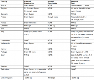
An extensive review of current legislation and practice for periodic inspection and pressure testing of cryogenic pressure vessels revealed a very wide difference of regulations between the European countries. A summary of the regulations at the time of publication is shown in Table 3. Due to the complexity of the regulations and the various qualifications and addenda, the summary tables can only indicate the general situation. The regulating bodies may have introduced changes during the review period. Therefore users of this document should refer to the latest legislation of the country in question. As an example, the periodic inspection and pressure test requirements for cryogenic pressure vessels for Finland, the Netherlands, and the United Kingdom are:
Table 3. Periodic Inspection and Test (Status as of January 2003.)
Summary of re-testing practice – Cryogenic pressure vessels



No comment